Polygons, Vertices and Meshes: The Anatomy of a 3D Model
Every 3D model, however ornate, is a list of points and a list of triangles that join them. Understanding that humble structure explains seams, hard edges, vertex counts and much of what a renderer actually does.
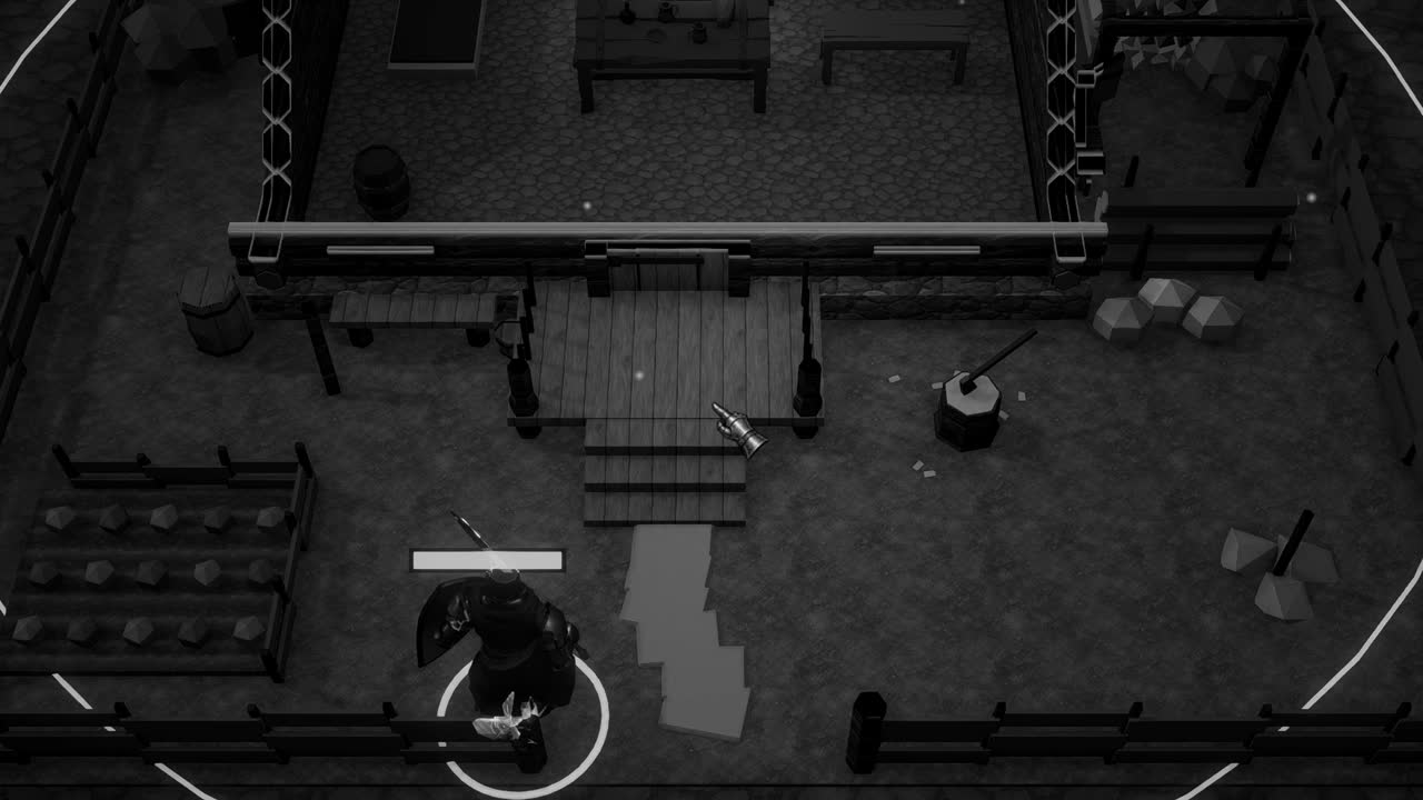
When we look at a figure in a game, a knight in dented mail or a cottage with a sagging roof, we see a solid thing with weight and surface. The graphics card sees nothing of the kind. It receives a list of points floating in space and a second list saying which of those points should be joined into triangles, and from these two dry inventories, together with a few images and some short programs, it produces everything the eye later mistakes for substance.
This structure, the mesh, is the common currency of real time 3D. It passes from the modelling program to the engine to the graphics hardware, and at every stage its form shapes what is possible and what is expensive. Artists who understand it make models that import cleanly and render cheaply; programmers who understand it can generate terrain, deform bodies and diagnose the curious seams and black faces that appear when the structure is misunderstood.
The anatomy is not complicated, but it contains a few surprises, chief among them the discovery that a simple cube is usually stored with not eight corners but twenty four. Following that surprise to its cause reveals most of what there is to know about how meshes really work, and why the numbers an artist sees in a modelling program so rarely match the numbers an engine reports.
Points, lines and faces
The vocabulary begins with three words. A vertex is a point in space, given by three coordinates. An edge is the straight segment between two vertices. A face is a flat polygon bounded by edges, the smallest piece of surface the model contains. A mesh is a collection of faces that together approximate the skin of an object; it has no interior, no mass and no notion of being solid, only a surface as thin as a soap bubble and considerably less forgiving.
Curved objects are therefore always approximations. A barrel is a ring of flat panels, a head is a few thousand small facets, and the smoothness we perceive comes from having enough faces that the angles between them become too small to notice, aided by lighting tricks that disguise the remaining corners. The number of faces, often called the polygon count, is one of the first measures of a model's cost, though as we shall see, the vertex count that the hardware actually processes can differ from what the modelling program reports.
Faces have two sides, and the renderer cares very much which is which. By default most engines draw only the front side of each face and discard the back, a saving called backface culling. A model whose faces point the wrong way will appear with holes, as though parts of it had been cut away, while the inside of the object shows through. Such errors, called flipped normals, are a classic sign of a modelling mistake or a careless mirror operation.
Why triangles
Graphics hardware renders triangles, and nothing else. The reason is geometric. Three points always lie on one plane, so a triangle is always flat, always convex and never ambiguous; it can be filled pixel by pixel with simple, fast arithmetic. A four sided polygon offers no such guarantee. Its fourth point may lie off the plane of the other three, in which case the face is bent, and there are two different ways to split it into flat pieces, which may look noticeably different under light.
Artists nevertheless model mostly in quads, four sided faces, and for good reasons. Quads arrange themselves into tidy rows and columns called edge loops, which follow the contours of a face around the eyes and mouth or the bend of an elbow, and which deform cleanly when a skeleton bends the mesh. Subdivision surfaces, which smooth a coarse cage into a refined surface, behave predictably on quads and erratically on triangles and on polygons with more than four sides.
The two worlds meet at export or import, when every quad is split into two triangles and every larger polygon into several. Unity triangulates meshes on import, so what reaches the graphics card is always a triangle list. Experienced artists check the triangulation of important areas before export, because a quad split along the wrong diagonal on a bent surface can create a visible crease, especially on characters where the mesh bends and the diagonal choice suddenly matters.
Sharing with indices
A naive way to store triangles would be to list three full vertices for each one. In a closed surface, though, each vertex is typically shared by several triangles, often around six in a regular grid, so the naive method stores most vertices many times over. The usual solution is the index buffer. Vertices are stored once in a vertex buffer, and each triangle is described by three integers that point into that buffer. In Unity these integers are what the Mesh.triangles array holds.
The saving can be calculated. Suppose each vertex carries a position, a normal, a tangent and one set of texture coordinates: twelve bytes, twelve bytes, sixteen bytes and eight bytes, for forty eight bytes per vertex. A hard edged cube, described below, needs 24 unique vertices and 12 triangles. Stored with indices it occupies 24 times 48, which is 1152 bytes of vertex data, plus 36 indices of two bytes each, 72 bytes. Stored without indices it would need 36 full vertices, or 1728 bytes.
The benefit goes beyond memory. Modern graphics hardware keeps a small cache of recently transformed vertices, and when an index refers to a vertex already processed, the vertex shader need not run again. Meshes whose triangles are ordered so that nearby triangles reuse the same vertices run measurably faster, and Unity can reorder triangle indices for this purpose during import, an option exposed in the model import settings.
The order in which a triangle's three indices are listed also carries meaning. This winding order tells the renderer which side of the triangle is the front. Unity treats triangles whose vertices appear clockwise, as seen by the viewer, as front facing. A procedural mesh written with its indices in the opposite order will vanish when viewed from the intended side and appear only from behind, which is a disconcerting first experience for anyone generating geometry from code.
What a vertex carries
A vertex is more than a position. It carries a bundle of vertex attributes, each read by the shaders that draw the mesh. In Unity's Mesh class these appear as parallel arrays: vertices for positions, normals for the direction the surface faces, uv for texture coordinates, colors for per vertex color, and tangents for the direction along which texture space runs across the surface. Additional sets of texture coordinates, uv2 and beyond, often hold lightmap coordinates or custom data.
The normal is the attribute that most affects how a surface looks under light. Lighting calculations ask how directly a surface faces a light, and the answer comes from the normal, interpolated across each triangle from its three vertices. If neighbouring triangles share vertices and those vertices carry averaged normals, the interpolation smooths over the angle between faces, and a twelve sided cylinder can look round. Mesh.RecalculateNormals computes such averaged normals automatically from the triangles.
Texture coordinates map the surface onto a flat image, as though the model's skin had been cut along certain seams and pressed flat. Each vertex records which point of the texture belongs to it. The tangent, stored as a four component vector whose fourth value records handedness, is needed when a shader applies a normal map, because it defines the local axes along which the map's directions are interpreted. Colors, finally, can tint the surface or carry masks for blending between materials.
Hard edges and split vertices
Here lies the answer to the cube with twenty four corners. A vertex holds exactly one value for each attribute: one position, one normal, one texture coordinate. A cube's corner is shared by three faces that point in three different directions, and if the cube is to look hard edged, each face needs its own normal at that corner. One vertex cannot hold three normals, so the corner must be stored as three vertices at the same position, each with a different normal.
Eight corners times three faces gives twenty four vertices. Each of the six faces then consists of two triangles, giving twelve triangles and thirty six indices. If instead the cube used only eight vertices with averaged normals, the lighting would shade it as though it were a lumpy sphere, its edges blurred into gradients, which is precisely the soft look that hard surface objects should avoid. Modelling programs control this through smoothing groups or edge sharpness, and these settings determine where vertices are split on export.
The same splitting happens wherever any attribute must change abruptly. A UV seam, where the unwrapped skin was cut, requires vertices along the cut to be duplicated, because a vertex on the seam belongs to two different places in the texture. Abrupt changes in vertex color do the same. This is why the vertex count reported by Unity's statistics often exceeds the count shown in the modelling program, which counts geometric points rather than the unique combinations of attributes the hardware must receive.
The Mesh in Unity
In Unity a mesh is an instance of the Mesh class, displayed by a MeshFilter and a MeshRenderer, or by a SkinnedMeshRenderer for meshes deformed by bones. A mesh can be built entirely from code by assigning arrays to vertices, triangles, normals and uv, then calling RecalculateBounds so that culling knows the mesh's extent. For larger or more frequent updates, the newer SetVertexBufferData and SetIndexBufferData methods give more direct control over layout and avoid some overhead.
By default a Unity mesh uses a 16 bit index buffer, in which each index is an unsigned integer between 0 and 65535. A mesh can therefore reference at most 65535 vertices in this format. Setting Mesh.indexFormat to IndexFormat.UInt32 switches to 32 bit indices, raising the limit to roughly four billion vertices, at the cost of doubled index memory and lack of support on some older mobile hardware. Model import settings expose the same choice, and large terrains or scanned objects routinely need it.
These limits and costs echo through every decision about geometry. A settlement scene in a game like Crown & Ashes, crowded with cottages, fences and villagers under torchlight, is ultimately a heap of vertex buffers and index lists submitted to the graphics card, and its performance depends as much on how many vertices the hard edges and seams have multiplied as on the triangle count an artist sees. Knowing the anatomy turns those numbers from mysteries into consequences that can be predicted and planned.